How to replace Dynamo with Alternator
Ok there
is nothing wrong with a properly
maintained dynamo and control box on
your imp, but only if they have been properly maintained! But either
way fitting an alternator is a good
idea as they are generally more
reliable and charge even when the
engine is idling - great for the
times you get in traffic these days.
Tools Required
Soldering Iron, Crimp Tool (correct
tool for the terminals you intend to
use), wire cutter and wire stripper
, 1/2AF sockets and spanners, 12"
straight edge, general tools
Supplies Required
Lucas Alternator Plug, 2 metres of
6mm2 wire (Red or Brown), 2 metres
of 1mm2 wire (Brown/Yellow or
Brown), a proper rear alternator
bracket but if you do not have one
of those the get some steel tube
with clearance for 5/16UNF bolts
though the centre (one like the one
between the water pump alloy and
steel brackets will do, lots of
'heavy' and 'standard' 5/16 flat
washers, some assorted 5/16UNF bolts
and nuts, some wiring loom tape (NOT
insulation tape!)/ flexi conduit
and/or cable ties, electrical test
lamp, new fan belt either an 1125 or
an 1137 (HB1125 and HB1137 at
Halfords) (buy both and return the
one that does not fit). Electrical
Terminals Pref an 5/16 / 8mm ring
terminal to suit the 6mm2 cable or
failing that a decent 10mm female
blade (lucar) connector and a male
and female blade connector with
insulation for the 1mm2 wire (bullet
connectors are also an option). You
may also wish to have a flask of
weak lemon drink to hand. (The
hobbies of Simon Quinlank)
Parts
Most alternators from the scrap yard
will work, but many these days are
huge due to all the electrical loads
on modern cars, the item that was
factory fitted to the very last Imps
is the Lucas LRA100, it was also
fitted to a number of British cars
of the same era, such as Mini's and
Viva's. Many people have also
sucessfully fitted the alternator
fitted to 80's and 90's Mini and
Metro's as they are still quite
small in size. For this article we
will be fitting the Lucas LRA100.
Section 1 - Mounting the Alternator
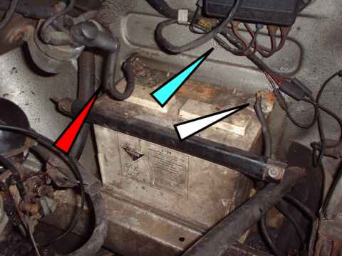
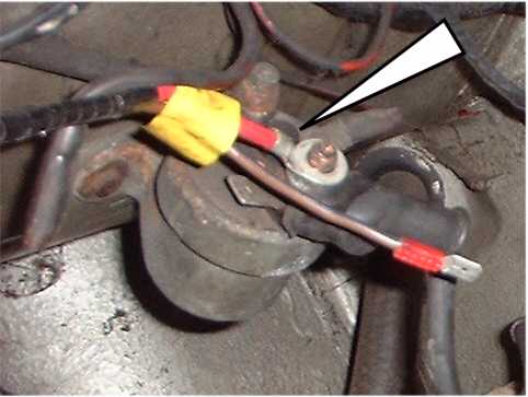
- First job when doing this is to
disconnect the battery negative
terminal (white arrow) do not do any electrical work on
you car without doing this! if you can't see which is the
negative terminal if you car is
a bit grubby, on a negative
earth car (as most imps are)
then is the wire connected to
the chassis, on an imp this the
point of attachment is a 7/16UNF
thread hole at the end of the
white arrow. The positive
battery lead is on a negative
earth car is the one that goes
to the solenoid (red arrow) See
Fig 1.
Fig 1
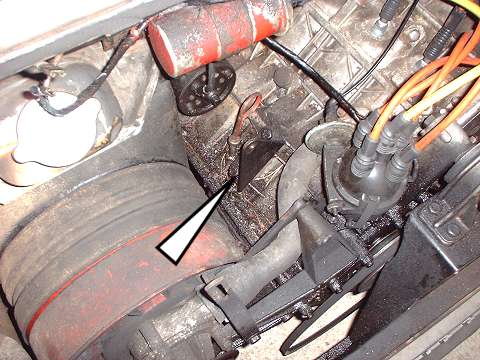
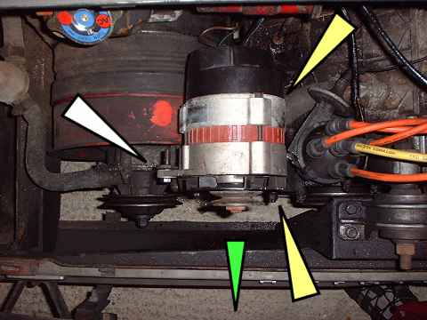
- Ok before we get involved with
the electrickery we need to do
some mechanical work. First
remove the dynamo. Slacken of
the bolts using your 1/2AF tools
as indicated in Fig 2. You will
also need to slacken of the bolt
indicated in Fig 3.
Fig 2

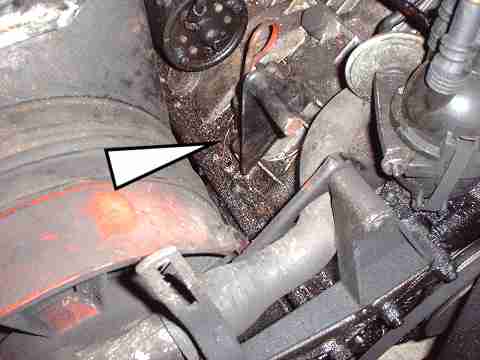
- You will also need to slacken of
the bolt indicated in Fig 2.
Then rotate the dynamo to
slacken the fan belt and then
remove the belt.
Fig 3
- Next reach round to the back of
the dynamo and disconnect the
large wire and small wire, these
should just pull off as they are
lucar (blade) connectors (Don't
be surprised id they literal
fall of - they did here!)
Now remove all the bolts
indicated in Fig 2, support to
dynamo while you do this to stop
it dropping away and watch your
fingers.
- With the dynamo removed you can
see rear dynamo support as
indicated in Fig 3. Now either:
- If you have a proper rear
alternator support bracket,
then you will need to remove
this bracket
or
- If you do not have the
proper rear alternator
bracket leave this one in
place as you can adapt it to
suit the alternator.
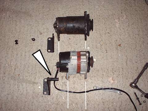
- Ok the next step is to stepback
and have a look at the
differences between the dymano
and the alt. As you see in FIg
4, the alternator is quite a bit
shorter than the dynamo. The
relation ship between the dynamo
pulley and the dynamo front
mount is nearly but not quite
the same as the alternator - the
alternator is more compact
generally apart from the
diameter! You can also see in
this picture the different rear
support brackets. The one we are
using is not a proper factory
support (this was a pressed
item) but a dynamo bracket that
has has a steel tube
welded/brazed to it to make the
distance up.
Fig 4
- Right if you have a proper rear
alternator bracket (or even a
modfied one like ours) then fit
this to the block - do not
tighten the bolts up fully at
this point as you might need to
move it around a little.
Fig 5
- Ok I can already hear some of
saying "Hey I don't
have a proper bracket, only the
old dynamo one!". Right
well for you guys this is where
the little piece of steel tube
comes in. As stated above in the
supplies listing a spare one of
those spacer tubes that normally
lives between the water pump
alloy and steel brackets is just
the job. Failing that you can
buy short bits of tube at you
local B&Q (other DIY
stores are availbale!). Just buy
a bit of steel tube (not iron or
gas pipe!) that a 5/16UNF will
fit into (take a bolt with you
to check) and try and get some
tube with thickish walls.
Failing both those options you
can (if you are a bodger at
heart!) use loads of heavy 5/16
(8mm) washers to make the gap
you, but unless you are called
Steve best get some tube!
*Tip, you will need to cut the
tube to the correct length you
need to get a nice square cut,
for this you can use a pipe
cutter (plumbing one will do
steel if you go slow). If you
don't have a pipe cutter, then
if you put a pipe clip (jubilee
etc) over the tube and tighten
it up it will give you a nice
square edge to cut againts with
your hacksaw, then just neaten
up/deburr with a file.
- Right time to mount the
alternator. It basically fits in
the same way as the dynamo, fit
the bolts to the main mounting
points first (yellow arrows Fig
6), you will need a longer
5/16UNF bolt for the rear mount
to take into account the steel
tube/rear alternator bracket
Because the distance between the
alternator and the front mount
is shorter that the dynamo, you
will need to add some washers
between the front alternator
mounting the cast alloy water
pump bracket in order to move
the alternator in the direction
of the green arrow. Nip the
bolts up (yellow arrows) so the
alternator is not wobbling
around. Then stand above the
above the alternator pulley and
visually site to see if it is in
line with the water pump/crank
pulley's. Get it close enough
using this method, you can fine
tune the alignment later. Put
the bolt in as per the white
arrow in Fig 6, you may need to
bend the adjustment bracket a
little to meet the alternator or
use washers.
Fig 6
- So now we have the basic
mechanical work done with apart
from fine tuning the alignment,
belt fitting and tightening up
all the bolts which we will do
later....it is time to move onto
the electrics! But first if you have your flask
of weak lemon drink, DRINK IT
NOW! YES ALL OF IT!
Section 2 - Electrickery
- Ok just in case you have got
this far without dissconnecting
the battery DO IT NOW! refer to point
of section one above. You should
never do any electrical work on
your imp without doing this
first, especially as they are
normally not fitted with any
fuses, your imp could end up a
burnt out wreck if you create a
short with the battery still
connected!
- First job is to make up the new
alternator cable, for this you
need to the two lengths of wire
(6mm2 and 1mm2), the alternator
plug kit, the loom tape/cable
ties/flexi conduit, the 8mm ring
terminal and the terminals you
have chosen for the thin 1mm2
wire). Now normally I perfer to
crimp connectors onto wire (as
long as you good quality crimps
and tool that is!) but in this
case I prefer to solder the
alternator terminals on the
wire, manily due to the fact
that the Lucar terminals are
'flags' (that is the wire comes
in at 90degs to the terminal)
and my crimp tool does not like,
and soldering is quick, plus
more people are likely to have a
soldering iron than a proper
crimp tool! I don't intend to
give a full lesson on soldering
here, or teach people to suck
eggs, but just a quick run down
and some tips.
- 'Tin' each part. Strip
insulation from one end of
each of the two wires and
tin the conductor, then tin
the terminals.
- Clean and tin the solderin
iron tip, this helps with
the heat transfer.
- Always heat the part to be
tinned up with the soldering
iron.
- Always feed the solder into
the item to be tinned when
it is hot enough, never melt
the solder directly with the
soldering iron..
- The solder should look
bright and shiny, if it is
dull and grey, it was not
hot enough.
- Place tinned parts together,
you can fold the crimp ears
around the wire using long
nose pliers, then heat
assembly, feed extra solder
into the assembly, when
solder flows remove heat and
keep assembly still until
cooled, joint should be
shiny and smooth, not grey
and dull.
- the big terminal is for the
6mm2 wire and the little one
for the 1mm2 wire!
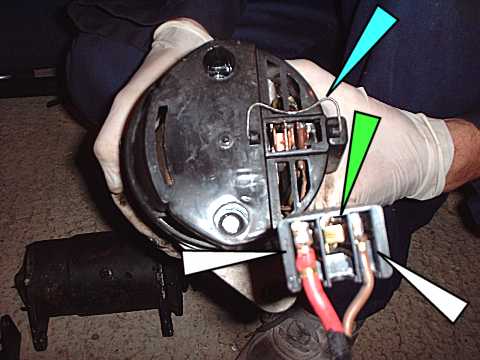
- once the solder has cooled, you
can assemble the terminal into
the alternator plug. You will
notice that there is space for
two large flags and one small,
push the small Lucar terminal
into the alternator pluh housing
until it clicks. Then insert the
large Lucar flag into the
alternator plug (Fig 7), it does
not matter which you use. Then
also insert the spare large
Lucar flag in the empty terminal
(green arrow), nothing
electrical about this last step
but will help stop the
alternator plug coming loose if
you no not have a alternator
plug clip (blue arrow). Be sure
to push all the terminal into
the housing until they click.
Then clip the back of the plug
on.
Fig 7
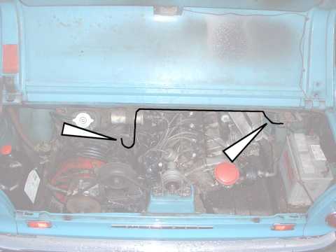
- Now before you fit the new loom
you need to get to the right
length, so loosely plug the
alternator plug into the
alternator, then run the cables
as per Fig 8, just temp hold the
wires to the car etc with
string/tape/cables ties. Make
sure you put a bit of slack as
marked in Fig 8 by the arrows.
Fig 8
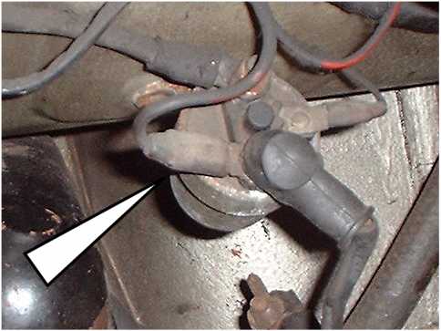
- Disconnect the large Lucar
terminal arrowed in Fig 9, just
tuck the wire and terminal out
of the way for now.
Fig 9
- Ok trim the 6mm2 cable to length
and crimp on the 8mm ring
terminal so that it will line up
with the post (the one that the
battery lead is attached to, and
NOT the one the starter cable is
attached to) on the solenoid as
per Fig 10. Ignore the thin in
Fig 10 for the time being.
Fig 10
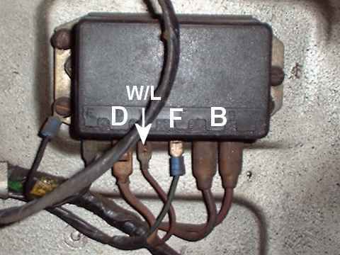
- Now onto the control box, Fig 11
show the item with clearer
terminal markings, you should be
able to see the markings moulded
into the black cover. It looks
confusing but is quite simple.
- 'D' - the fat wire connected
to terminal D is the other
end of the fat wire that
used to go to the back of
the dynamo
- 'W/L' - Simple this one, W/L
is the wire that goes to the
little red light on the
dashboard or in the binnicle
- 'F' - the thin wire
connected to terminal F is
the other end of the thin
wire that used to go to the
back of the dynamo
- 'B' - One of these fat wires
goes to the ignition switch,
the other goes to the
solenoid and is the one you
disconnected in Fig 9
Fig 11
Terminal 'B' is a common
terminal so it does not matter
which way round the two fat
wires are conected, but you need
to know which is which! First
disconnect the two wires from
the control box. Method one is
to connect a powered test lamp
or continuity tester (on every
digital multimeter) to the
terminal you disconnected in Fig
9 above then buzz out the two
wires you have just disconnected
from the control box one at a
time - the one that lights the
lamp or sounds the buzzer is the
wire YOU DO NOT NEED, mark both
ends of his wire with
tape/marker pen so you know
which it is (we will call this
wire the solenoid wire). If you
don't have a test lamp or a
continuity tester you can ID the
wires physically by unwraping
the loom and seeing which is
which, you want the fat brown
wire that goes between the 'B'
terminal and that dissappears
with the rest of the loom into
the car (we will call this the
wire the power wire) and NOT the
fat brown wire that goes to the
solenoid (solenoid wire).
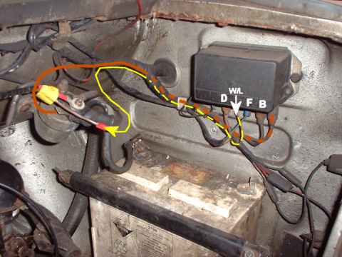
- Now unwrap the loom and move the
'power'fat wire and the thinner
brown/yellow wire that was
connected to W/L from their
current positions marked with
dotted lines (Fig 12) to their
new positions marked with solid
lines (Fig 12). You will not now
the fat brown wire goes to large
(10mm) male lucar terminal, you
may need to trim the length of
the wire a little and also check
the condition of the terminal on
the end of the fat brown wire,
if in doubt replace with a new
10mm female lucar terminal. You
will also note that the thin
brown wire with the yellow strip
or 'tracer' needs connecting to
the thin wire in you newly made
alternator loom. You can make
this connection with a male and
female lucar terminals of bullet
terminals, now you can trim the
thin wire in yoru alternator
loom to length. Ok that is the
difficult electrical bit done,
now you just need to make good
all the connections and tidy the
wiring up.
Fig 12
- Remove the alternator loom and
wrap with loom tape (remember DO
NOT use insulation tape it is
rubbish for this job), or bundle
the alternator loom together
with cable ties at regular
intervals, or run the wires
through some small diameter
flexi conduit. Then once you
have finished the loom you need
to clip and secure the loom to
the car, you can do this by
cable ties to the existing loom
bundle. Make sure you leave some
slack at the alternator end to
allow for engine movement, plus
the alternator plug firmly into
the alternator and then if you
have one pop the retaining clip
on. Now at the other end undo
and remove the nut and spring
washer on the solenoid post
(remember one the battery lead
is attached to) and fix the 8mm
ring terminal to the stud, refit
the washer and nut and tighten.
Reconnect up the thin wires and
bundle up with the rest of the
cars loom. You can now remove
the control box, you can leave
the old dynamo wire and the
'solenoid' wires in place just
tuck the ends out of the way and
wrap in loom tape (you could of
course remove all the redundant
wires if you wished and then
rewrap all the engine bay wires
for a neat look)
Section 3 - Aligning the Alternator
pulley
- You might remember that the
alternator is roughly mounted in
place, but it needs to be
aligned as accurately as
possible to ensure the water
pump and alternator bearings are
no overloaded and the belt does
not wear out too quickly.
- As per Fig 6 above the main
mounting bolts should be fairly
tight, you now need to check the
alignment of the alterntor
pulley in relation to the water
and crank pulley's - getting
this wrong with at best wear the
fan belt rapidly or at worst
loose it and also damage the
alt/water pump bearings. Make
sure the main mounting bolts (so
the alternator is not tipping)
are tight fit a fan belt then
swing the alternator up to make
the belt tight.use a straight
edge such as a steel rule to
check alignment. (fig 13)
Fig 13

- insert/remove washers in the
area indicated to get the
correct alignment - a little tip
is get a selection of 'heavy'
and 'standard' 5/16 washers as
they are different thicknesses;
useful for gettingthe right
thickness ie two thick, one
thick one thin, two thick one
this etc.
It is also worth using the steel
rule in other planes plus
sighting along the fan belt runs
to check the alignment.
Section 4 - Testing
- Ok adjust up the alternator
using the adjuster bracket to
get the correct fan belt tension
(about 1" slack in the
centre of the longest run water
pump to crank pulley)
- Make sure all the mountings are
tight.
- Make sure the alternator plug is
fitted in to the back of the alt
- Make sure the other electrial
conections are correct, spinning
the alt up with out it being
connected up WILL DAMAGE IT
- Make sure the noting is going to
dangle / get tangles up in the
engine (such as the old wiring
if you have left it in place).
- Reconnect the battery - Nothing
should happen at this point!
- Ok ready for a test. First check
that the ignition warninglight
is not blown - this is now an
essential part of the new
charging circuit - if it is
blown the alternator will not
work properly (see Aldrins
comment - a resistor is a good
idea).
- Turn the ignition key one click
- the ignition (red) warning
light should light up.
- Start the car, the red light
should now go out! Ifit does not
there is a problem -switch off
and investigate. If it does got
out you can also check the
output by using multi meter
across the battery even at a
fast idle voltage should be
13volts +
(c) Andy Smith 2025
